The Technology
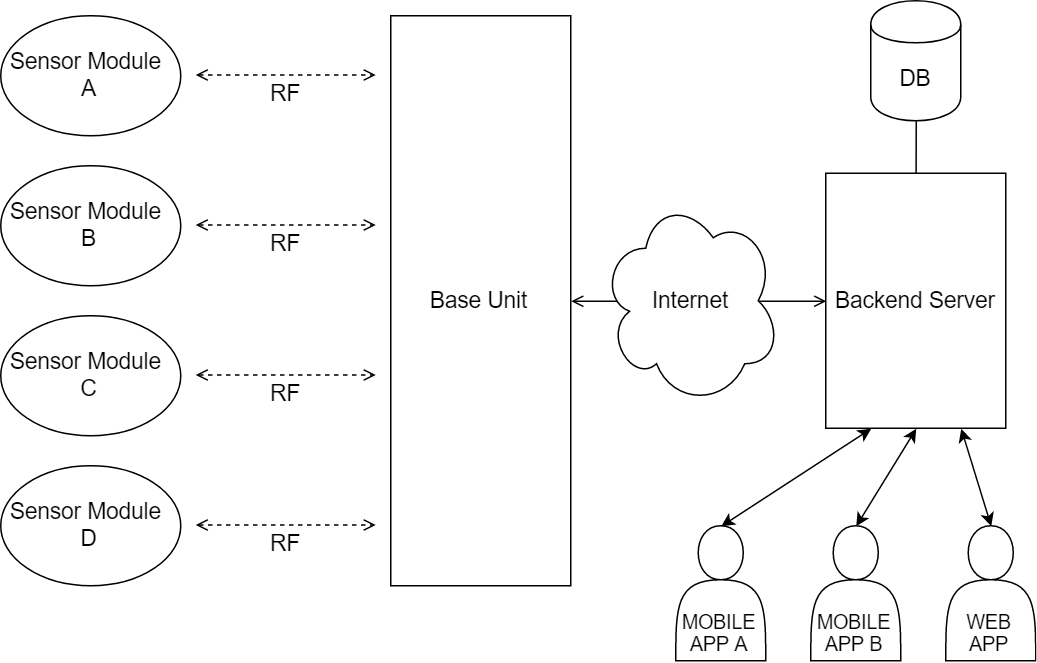
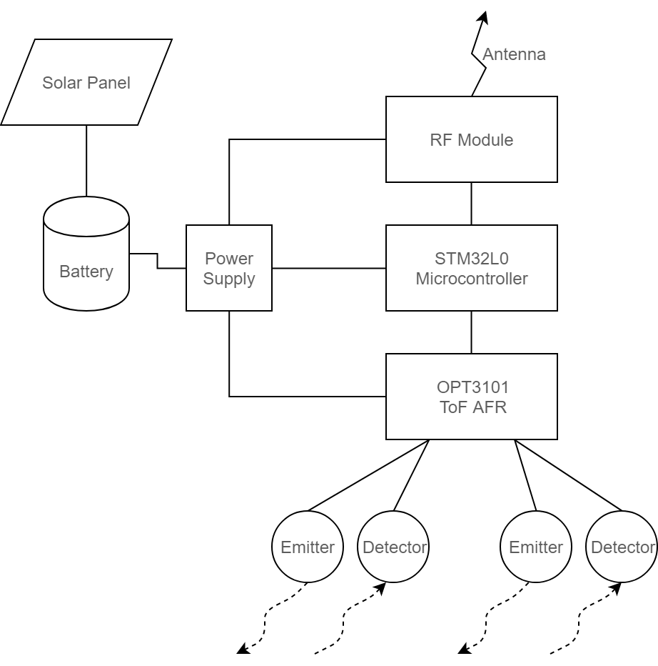
The project is based on a differential counting of the vehicles going into and out of a parking lot. Counting is done by wireless sensor modules located at each entrance and exit point. Each module consists of a a pair of sensors, an RF transceiver, a small microprocessor board, a battery, and a solar panel. All modules communicate with a base unit which receives raw data over RF and sends that data to the Internet-based backend server. Data is processed and stored in the server, and is accessed by user friendly apps or a web interface. The following diagrams show, at a high level, the different components of the system and how they interconnect, and the internal blocks of a sensor module:
Vehicle Detection
We chose to implement the optical ToF technology in our project as this provides the best performance and features compared to other technologies. Our sensor module is based on the OPT3101 ToF analog front end (AFE), which is a state-of-the-art IC and is currently only available as preview samples. The following figure illustrates the proposed configuration of the sensor module, where two optical sensors are used to detect vehicle movement direction and ignore smaller objects:
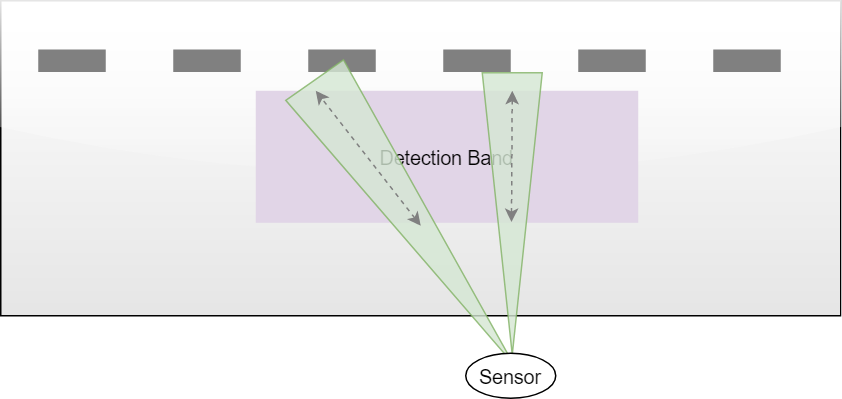
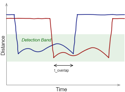
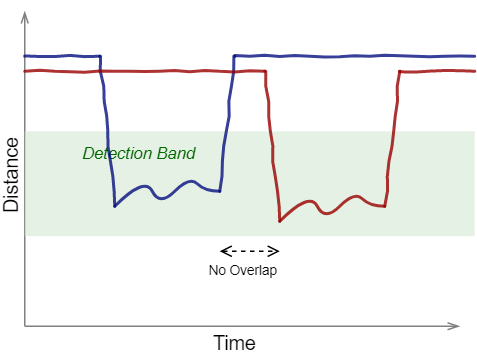
Distinguishing between large objects (cars) and small objects (pedestrians) is done by measuring the overlap between sensor readings. A minimum time of overlap is required to consider an object countable. The figure below shows how sensor readings may look like with small and large objects. The minimum overlap time requirement varies for different distance readings due to the projection angle between the sensors which creates an increasing gap between the sensors' fields of view.
The operation of the two sensors and the logic involved with determining a valid count will be done in-place, in the sensor module's microprocessor. Only valid counts will be sent forward to the base unit.
Communication
All sensor modules are capable of transmitting and receiving data using off-the-shelf 915MHz RF transceiver modules which are widely available. The modules have a range of up to several miles, include built-in signal encryption, and provide a simple interface with an MCU. We will develop our custom communication protocol for transmitting count data from sensor modules to the base unit. Other types of data will include periodic ping checks, maintenance warnings, battery status, and more. In case of lost communication, the sensor modules will be able to temporary store data in a transmit queue and retransmit it as soon as communication resumes again.
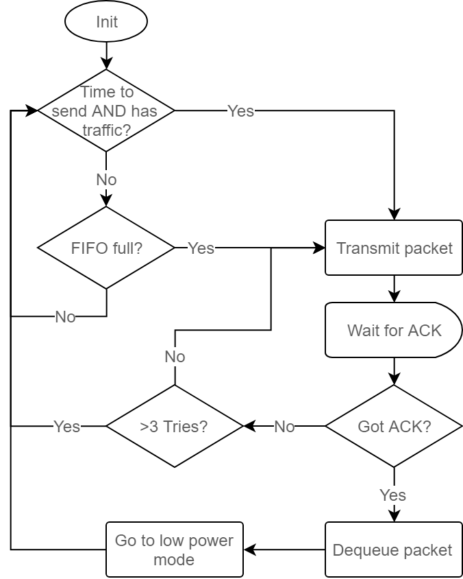
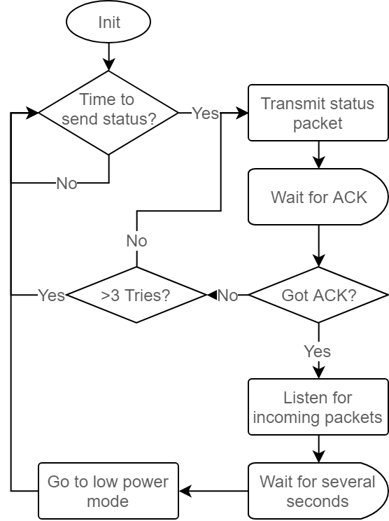
Per our custom communication protocol, the base unit is designed to always listen to incoming packets, while the sensor modules will only listen to packets for short periods of time after sending a status/ping message. In order to save battery charge, the sensor modules are designed to transmit packets at a low frequency, around once every minute, or not at all if no vehicle traffic was detected. Together with the regular traffic count packets, the modules transmit a status/ping packet once an hour. The packet contains basic status parameters such as the battery charge level and it is used to let the base module know that the sensor module is alive and functional. Shortly after transmitting the status packet, the sensor module listens for several seconds for any incoming packets in case the base module wants to send configuration or command packets back, and then finally it goes back to an idle/low power mode and being kept in that mode while not transmitting data. The following figure shows a high level logical flow of sending packets:
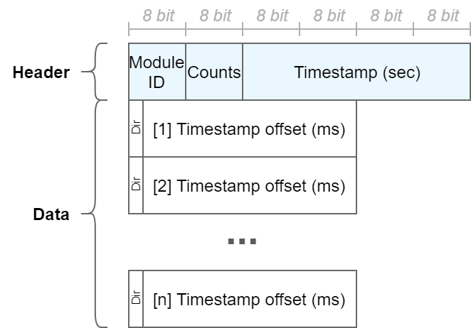
Traffic packets contain a header with the module ID, the number of counts and the current timestamp (seconds since the module was powered on), and an array of 32-bit values where each value represents a single vehicle count. The lower 31 bits of each value are the offset from the packet timestamp (in milliseconds) and the most significant bit of that 32-bit value represents the vehicle direction (in or out). The structure is demonstrated in the figure below:
The base unit will be connected to the internet through a cable, WiFi, or a cell network. It will be pushing all data collected from the sensor modules to the cloud server where it will be further processed.
User Interface
Our system will have an API that will be available publicly. Any third-party application can be developed to use the API. We will develop an example application for iOS devices and a web application that can be accessed from any browser.
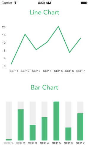
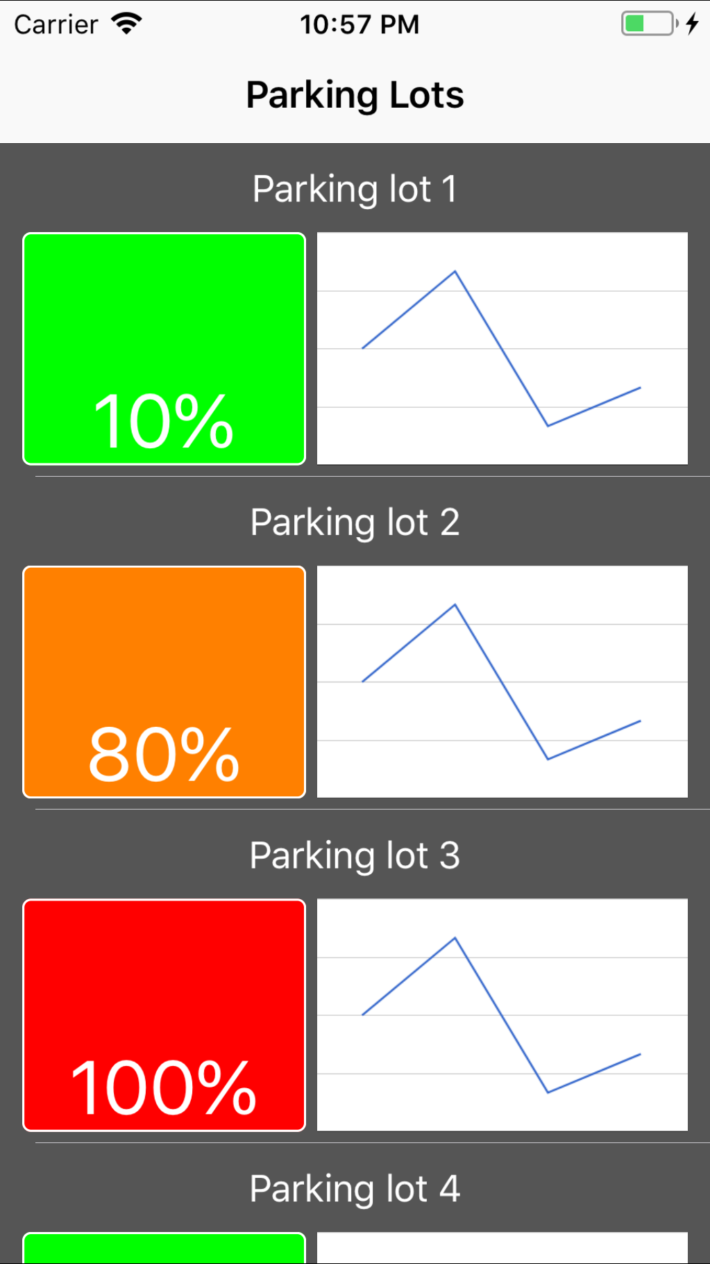
The application will present a list of parking lots and for each lot the estimated number of currently available parking stalls will be shown. Upon clicking on a specific parking lot, a detailed screen will be shown with graphs that show parking space availability over time and other statistics. The application will include a map that shows the lots and the available parking spaces.
The majority of the project such as sensors, server and database are all backend and the user does not get to see that. The user only needs to see relevant information of the parking lot and doesn't need to know what's happening behind the scenes. The iOS mobile app is built to create an appealing to an eye graphical representation of the database information. The app is the frontend of the project and the only thing the user actually sees. The user could perhaps see the individual sensors on each entrance and exit, but would not understand what they are for. This separation between the frontend and the backend allows the users to easily navigate and reach their wanted information as soon as possible. An example of how the user interface may look like is shown below: