MSE 5090: Case Studies in Material Selection
Week 9 - CMS Process Selection Formalism
Arrayed below are the figures presented on Wednesday 10/21/98 in
class. They depict the method used by the CMS software to categorize, sort
and plot various materials processed according to attributes of these
processes. The key to their use in the selection process involves obtaining
a congruence between the component attributes such as size, shape , finish,
cost etc. and those of an process. In other words , if a component requires
a surface finish of 1 micron and the process under consideration can only
yield surface finishes of 10 microns , then the incongruence will move
that process out of the selection space in the program.
In this regard , the outcomes of the material selection part of the
design process, coupled to the design requirements on the component that
were passed through from the customer form the constraints and design requirements
for the process . These form the screen from which the choices for acceptable
processes are narrowed.
 |
|
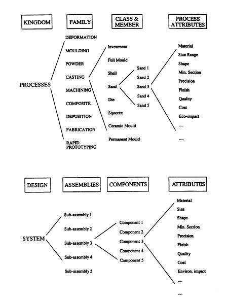
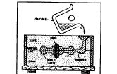
| Figure 1 (above) The classification of processes and (below) the breakdown of a component design. The method identifies processes with an attribute-profile which matches that required by the design. | |
 |
|
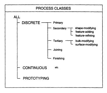
| Figure 2(a) The classification of process types. Each process is linked to one or more members of each. | |
 |
|
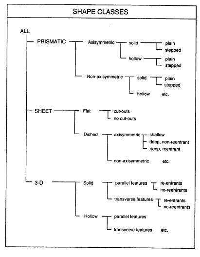
| Figure 2(c) The classification of shapes. Each process is linked to one or more members of each. | |
 |
|
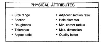
| Figure 3(a) Physical attributes of processes. | |
 |
|
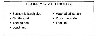
| Figure 3(b) Economic attributes of processes. |
Fig. 4: Below is a typical data record from the process data base. It describes a subset of the casting process.
| Name | CO2/silicate Process | Short Name | CO2/silicate |
| Designation | Casting: CO2/silicate | Identifier | QSASI_$$$ |
 |
Description: In the CO2/SILICATE process, a mixture of sand and sodium silicate binder is packed around a pattern that has the shape of the desired casting. C02 is introduced to the compacted sand whereupon the sodium silicate gels to produce a rigid mold. The pattern is then removed to leave the cavity in which molten metal is poured. When the metal solidifies, the mold is broken to retrieve the casting. The pattern is made of either wood, plastic or metal. The pattern is made slightly larger than the desired casting to compensate for shrinkage of the metal as it cools, If the casting is to he machined, a machining allowance is also added. The process is not widely used. Major reasons have been the problems of deterioration of molds and cores during storage and thc poor breakdown characteristics associated with the inorganic silicate bond. In addition, close control over process variables such as temperature, CO2 flow rate and gassing time is essential. |
| Physical | attributes | ||||
| Size range (extreme) | 1 | - | 1.00E+5 | kg | |
| Size range (normal) | 25 | - | 100 | kg | |
| Section (extreme) | 4 | - | 999 | mm | |
| Section (normal) | 5 | - | 999 | mm | |
| Roughness (extreme) | 6.3 | - | 50 | mm | |
| Roughness (normal) | 12.5 | - | 25 | mm | |
| Tolerance (extreme) | 0.8 | - | 3 | mm | |
| Tolerance (normal) | 1.2 | - | 3 | mm | |
| Aspect ratio | 1 | - | 20 | ||
| Adjacent section ratio | 1 | - | 5 | ||
| Hole diameter | 13 | - | 300 | mm | |
| Min. corner radius | 5 | - | 50 | mm | |
| Max. dimension | 100 | - | 3.00E+3 | mm | |
| Quality factor | 1 | - | 4 | ||
| Economic | attributes | ||||
| Economic batch size (units) | 1 | - | 1.00E+3 | units | |
| Economic batch size (weight) | 35 | - | 3.50E+4 | kg | |
| Capital cost | 1.0E+3 | - | 5.00E+3 | £ | |
| Tooling cost | 100 | - | 2.00E+3 | £ | |
| Lead time | 2 | - | 4 | weeks | |
| Material utilization fraction (0-1) | 0.5 | - | 0.7 | ||
| Production rate (units) | 0.1 | - | 5 | /hr | |
| Production rate (weight) | 3.5 | - | 175 | kg/hr | |
| Tool life (units) | 10 | - | 1 .00E+3 | units | |
| Tool life (weight) | 350 | - | 3.50E+4 | kg | |
| Material | Class | ||||
| M-ferrous | |||||
| M-light alloy | |||||
| M-nonferrous |
| Process | Class |
| DISCRETE | |
| P (PRIMARY) | |
| RAPID PROTOTYPING |
| Shape | Classes | |||
| PRISMATIC | --axisym | --solid | --plain
--stepped |
|
| --hollow | --plain
--stepped |
|||
| PRISMATIC | --nonaxisym | --solid | --plain
--stepped |
|
| --hollow | --plain
--stepped |
|||
| 3-D-solid | --parallel feature | --reentrant
--non reentrant |
||
| 3-D-solid | --transverse features | --reentrant
--non reentrant |
||
| 3-D-hollow | --parallel feature | --reentrant
--non reentrant |
||
| 3-D-hollow | --transverse features | --reentrant
--non reentrant |
Shape notes: Bosses, undercuts, inserts and hollow sections are all practical. Shapes are frequently solid but complex internal shapes can he made using cores.
Environmental notes: Safe and environmentally acceptable, however care is required in handling process chemicals and adequate ventilation required for C02. The binders are odorless, non-toxic, non-flammable and water-rinsable.
Notes: Minimum wall thickness depends on the alloy to be cast and the length of the section involved. Tolerances depend on the dimension - the values given apply to a 25 mm dimension.
Typical uses: Wide range of applications including machine tool castings, large engine blocks and heads. Process is also used for the mass production of cores.
References: G_ENAL001;G _ENBR001;G_ENKA001;G_ ENSC001;G_ENWA001
Figure 4
above .A typical record. It is that for a member of the casting family:
C02/Silicate Sand Casting.
Figure 5:The figure below describes how the process selection software allows the sequential selection of processes , through three steps here , based on process, material and shape process attributes.
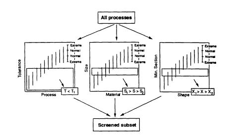 |
Figure
5 (a) The SCREENING stage. The attributes of processes are plotted as selection
charts, created by the software. The attributes specified by the designer
are plotted as selection boxes on the charts. The software retrieves
the subset of processes which meet all the required attributes.
Last update 10-21-98