(industry is starting to move toward a 3.3-volt power
supply). In digital systems, we assign logic 1 to "high" voltages
and 0 to "low" voltages, but these assignments are somewhat arbitrary. For TTL
technology of the kinds described in this book, a voltage in the range of 0 to
0.4 volts is interpreted as logic 0, while 2.5 to 5.5 volts is interpreted as a
logic 1. Voltages outside these ranges are not guaranteed to be interpreted as
either a 0 or a 1.

Charge measures the number of positive or negative charges at a given point
in the circuit and is described in units of coulombs. One coulomb is equivalent
to the charge on ![]() electrons. Voltage is the difference in electrical potential between two points
in a circuit and is measured in volts. At a given point in a circuit, current is
the change in charge as a function of time. Thus, one ampere is defined to be
one coulomb per second.
electrons. Voltage is the difference in electrical potential between two points
in a circuit and is measured in volts. At a given point in a circuit, current is
the change in charge as a function of time. Thus, one ampere is defined to be
one coulomb per second.
Resistance Figure B.1 introduces two
important new quantities: resistance and capacitance. Resistance is the
"friction" that limits current. Doubling resistance cuts the current in half.
When two resistors are connected in series, one immediately following the other,
their resistances add. Placing two resistors in parallel results in a resistance
that is less than the component resistances. To be more precise, if the
resistances, measured in ohms, are R1 and R2, the parallel
resistance will be ![]() .
.
A short circuit is a path of conductors with no
(or very low) resistance. An open circuit is a
conductive path with infinite resistance. Semiconductor materials make it
possible to construct connections between two points that can be varied between
low and high resistance.
One of the most important
expressions for analyzing electrical circuits is Ohm's law (for the
German scientist Georg Simon Ohm). It describes the relationship
between voltage (V), current
(I), and resistance
(R) as follows:![]()
To understand this relationship,
let's consider the water analogy again. V is the height of the
waterfall. We can think of R as inversely proportional to the diameter
of a water pipe: a high resistance corresponds to a narrow pipe, a low
resistance to a wide pipe. A narrow pipe restricts the flow more than a wide
pipe. With a high resistance, current is reduced, because fewer electrons can
move through the conductor per unit time. By reducing the resistance
(that is, increasing the cross section of the pipe),
we increase the flow of electrons.
An alternative
formulation of Ohm's law allows us to describe resistance as a function of
voltage and current: R = V/I. Thus, if a
power supply provides voltage V and the current is measured as
I, then the resistance of the circuit being driven by the power supply
is R.
Capacitance Capacitance is the ability to
store charge and is measured in units of farads (named for the
great 19th-century British scientist Michael Faraday). A capacitor
is a device with two parallel conducting plates separated by a nonconducting
material. Placing negative charges on one plate will attract positive charges to
the other plate. A capacitor uses current to charge the plates up slowly to a
new voltage. Once charge is stored, the capacitor can also provide a "discharge"
current to the rest of the circuit. Thus, capacitors are often used to smooth
out variations in the current provided by the circuit's power supply.
Continuing with our water analogy, a capacitor behaves much like a
water holding tank. A hole at the bottom of the tank provides a steady "outflow"
of current, even though the inflow may be sporadic.
Charge, voltage, and capacitance are related by![]()
Charge is equal to capacitance times
voltage. By placing a voltage V across a capacitor of C
farads, we can store a charge of Q coulombs.
RC Delay There is an interesting relationship between time, resistance, and capacitance. Consider how long it takes to charge up a discharged capacitor.

Figure B.2 shows a possible setup. In the schematic, the voltage source is labeled V, the resistor R, and the capacitor C.
We assume that the capacitor is completely discharged and the
switch is in the open position. When the switch is closed, the power supply
begins to charge up the capacitor toward the voltage Vchg. If you
measure the voltage across the capacitor with a voltmeter, initially the voltage
changes very quickly, but then it slows down.
There is a
precise relationship between the resistance and capacity of the circuit and the
time it takes to charge the capacitor. It is directly related to ![]() , also known as the RC time constant
, also known as the RC time constant (it may
seem strange that ohms times farads is seconds, but this is the
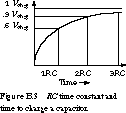
case). After one RC delay, the capacitor is charged up to
slightly more than 60% of its final value. After two RC delays, it
reaches almost 90% of its final value. It takes five RC delays before
the capacitor reaches 99% of its final value. This is shown in Figure B.3.

RC delays play an important role in determining the
true performance of digital circuits. Even though wires are excellent
conductors, they do present some resistance to the current flow. But even more
important, wires introduce capacitance: a wire forms one plate of a capacitor
whose second plate is the circuit board itself. Changes in voltages on wires
require this capacitance to be either charged or discharged, and this translates
into a significant source of delay in real circuits.
[Top]
[Next]
[Prev]